Practice - RO-BO Mechanical Workshop
Main menu
- Home Page
- Company
- Contacts Mail
- Coffee Grinder RW-70
-
Valves EN 15089
- Rotary valves EN 15089
- Main features
- Products
- Explosion barrier
- Images
- Certifications
- Valves TN/TS
- Valves TNA/TNAS
- Valves VP/VPC
- Atex valves
- Rotary valves
- Blow Through valves
- Food Indusry
- Diverting valves
- Rotary valves for microdispensing
- Interception valves
- Gearbox
- Spare parts - Works for third parties
- Collaborations
-
Restricted area
- Registration form
- Customers
- Service
Practice
PRACTICE
PRESSURE DROP RESULTING FROM A ROTARY VALVE IN A PNEUMATIC CONVEYOR SYSTEM
Correctly evaluate the loss of load of a rotary valve without having practical and reliable evidence during operation would already theoretically difficult but also realistically useless. In fact, experience shows that a blow-
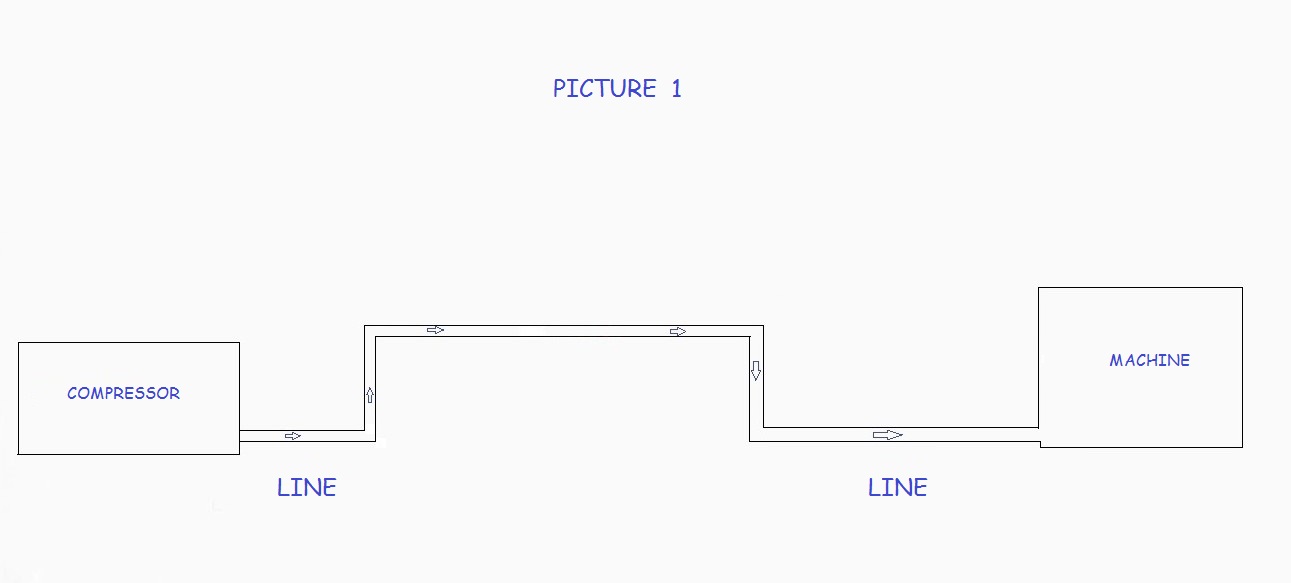
That said, to properly evaluate the behavior of our valves , we took advantage of the renovation of an existing plant to run some tests useful for this purpose : having the facility type ( Fig. 1) we performs the calculation of its theoretical pressure drop ( Report 2 ) obtaining the result of 0,543 bar.

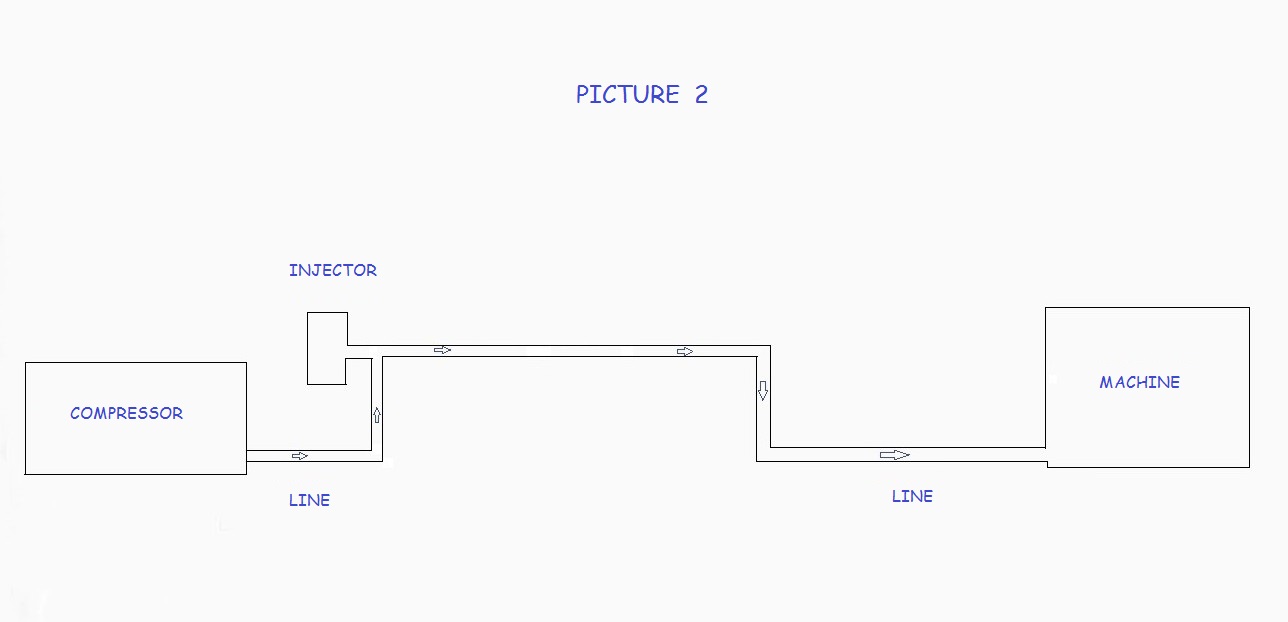
Then we carry out the verification controlling it instrumentally and inserting the solid to be transported via external injector (Fig. 2): in this case, being the plant new and properly made, the differences between theory and practice are negligible for which we can consider the value 0.543 true, but remember that is rarely the case, even in installations in operation from few months.

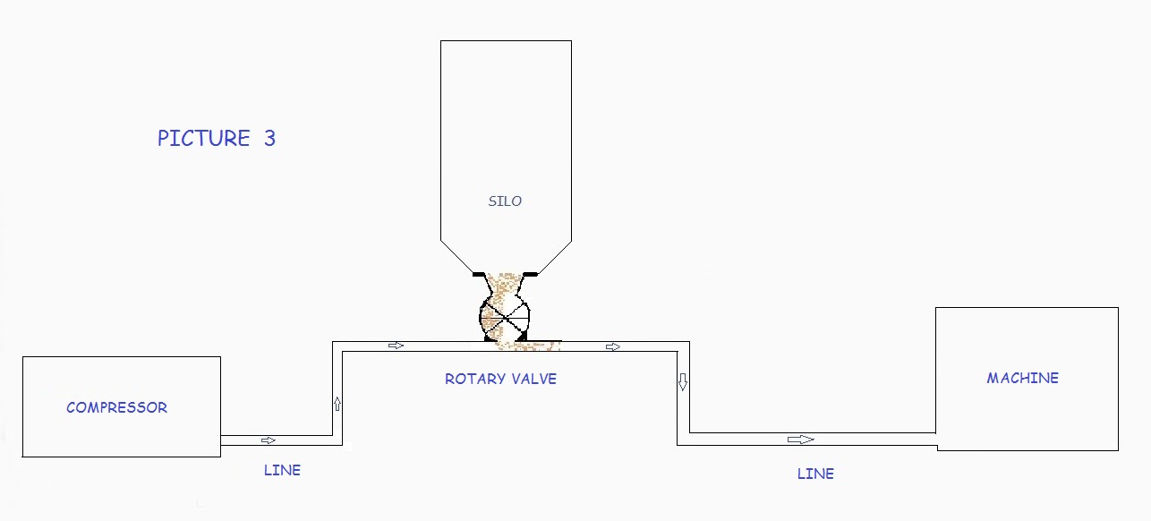
Now we insert a valve TN 20 in the line (Fig. 3), connected to a feeder silo. We chose this model because it has a pipe almost identical to those of the plant, very important factor, as we shall see later. Once done all the necessary checks, we measure the pressure drop: It is of 0.592 bar.

So, considering the previous measurement performed on the system without the valve and resulting in 0,543 bar, for difference is obtained that the loss of the valve is : 0.592 -
This obtained and shown, it is important to remark that this value is true and real ONLY AND ONLY IN THIS CASE. It would be enough to change even one of the elements (diameter pipes, bends number, length line, pipe roughness, etc..) To obtain different results.
To demonstrate this, I recalculated everything assuming to vary only the diameter of the pipe line components: from 50mm. to 40mm.
Well, the result is a loss of 0.857 bar that, in presence of the valve, worsens 1,036. Is therefore changed the behavior of the valve?
Certainly yes, but not for reasons attributable to the valve itself, but for the bad matching with the line. In short, it is sufficient to know that the variation of the diameter of a pipe from smaller to larger (40 to 50 mm) creates pressure loss and dispersed flows, while the opposite (50 to 40) creates reflections flows and waves against flow rate and other effects that we'll consider more carefully in a future analysis.
Now, suffice to understand that we have both of these negative components in the limited portion of the pipe (about 70 -
So well you understand, even without mathematical equations and formulas, the reason why the behavior of the valve is worse.

